


What components does Power & Free Conveyor consist of?
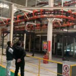
The Power & Free Conveyor is a type of transportation equipment suitable for high-productivity, flexible production systems. It not only serves as a transportation tool but also runs throughout the entire production line, integrating sophisticated process operations, storage, and transportation functions. With the rapid development of modern logistics and transportation technology, the Power & Free Conveyor has been widely used in various industries, particularly in the automotive industry, where it is used in four-door assembly lines, engine assembly lines, vehicle assembly lines, and body painting lines.
1.1.Power & Free Conveyor Structure:
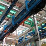
A power and free conveyor primarily consists of the following components: power and free track, traction chain, power and free trolley, drive unit, tension unit, stop stations, slewing mechanism, switch junctions, and gas control unit. The following describes its structure in detail.
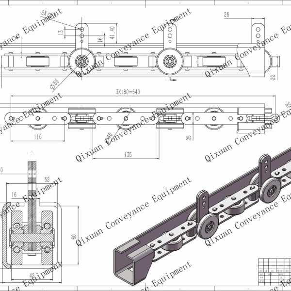
1. Power and free track: A power and free conveyor system uses different track types and different track spacings. The track in a power and free conveyor system consists of two layers. The upper layer is the traction rail, which transmits traction power. Above it, the support rail is made of I-beams of varying specifications. The inner surface of its lower flange serves as the tread for the traction chain carriage rollers, which support the trolley frame through the chain. The lower layer is the support rail, constructed from two specially made channel steels. The lower flange of the support rail serves as the tread for the trolley wheels and guide wheels. The trolley is propelled along it by the pusher head on the traction chain, and the trolley is suspended from the trolley by a special sling.
1.Power & Free Track Types (by Rail Spacing) Power & Free (P&F) tracks are categorized into three types based on rail spacing:
1.1 Lift Track: The trolley’s ”lifting dog” does not engage with the conveyor chain’s ”pusher dog” due to wider rail spacing. Used during chain transfers to prevent trolleys from pushing the chain .
1.2 Accumulation Track:Narrower spacing ensures the pusher dog engages the ”backstop dog”. When the pusher dog contacts the backstop dog’s rear, the backstop dog lowers, allowing the chain to override it. This prevents trolleys from surging ahead .
1.3 ”Compression Track”:Minimal spacing forces the pusher dog to remain fully between the lifting dog and backstop dog. Ensures ”positive engagement” on vertical curves and during chain transfers, eliminating disengagement risks on inclines Vertical Curves”Refers to ”inclined/declined sections”. P&F vertical curves ”must” use compression track for safety .
2. Hangers:”Connect ”traction track” (upper) and ”load track” (lower). Support trolleys, loads, chain, and track weight. Hanger thickness is load-dependent .
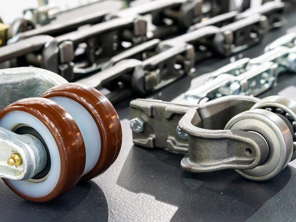
3. Traction Chain: Primary drive mechanism. Comprises precision die-forged components: outer/inner link plates, pins, ”pusher dog link plates”, and ”chain support trolleys”. Made of alloy steel, heat-treated, and NDT-inspected for high reliability .
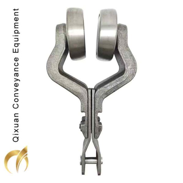
4. Power & Free (P&F) Trolley Train”- ”Load bar” connects to ”load carriers” on the load track.- ”Lead trolley” engages/disengages via the ”lifting dog”.
– Stops when:
– Lead trolley contacts a ”stopper” with extended ”stop arm”.
– Lead trolley bumps into a stopped trolley train, causing accumulation .
– Stopper action:
– Extended stop arm depresses lifting dog →”disengagement”.
– Retracted stop arm allows lifting dog rise → ”engagement” .
4.1 Lead Trolley”
-”Guide trolley” propelled by pusher dogs.
– Unique ”lifting dog” enables engagement/disengagement.
– In ”wide-dog P&F systems”, lifting dog and backstop dog are integrated .
5. Drive Station: The drive station provides power to the traction chain. It consists of:
-”Motor”
– ”Gear reducer”
– ”Drive frame”
– ”Drive chain assembly”
The motor connects to the reducer via V-belts. In ”crawler-type drives”:
– ”Drive sprocket” (connected to reducer output shaft)
– ”Idler sprocket” (tensioning sprocket)
– ”Drive chain” transmitting power to the traction chain
Features ”dual protection”: mechanical overload clutch + thermal overload relay.
6. Take-Up Unit: Absorbs chain slack caused by wear or thermal expansion, maintaining constant tension. Always positioned at the ”chain exit end”of the drive station.
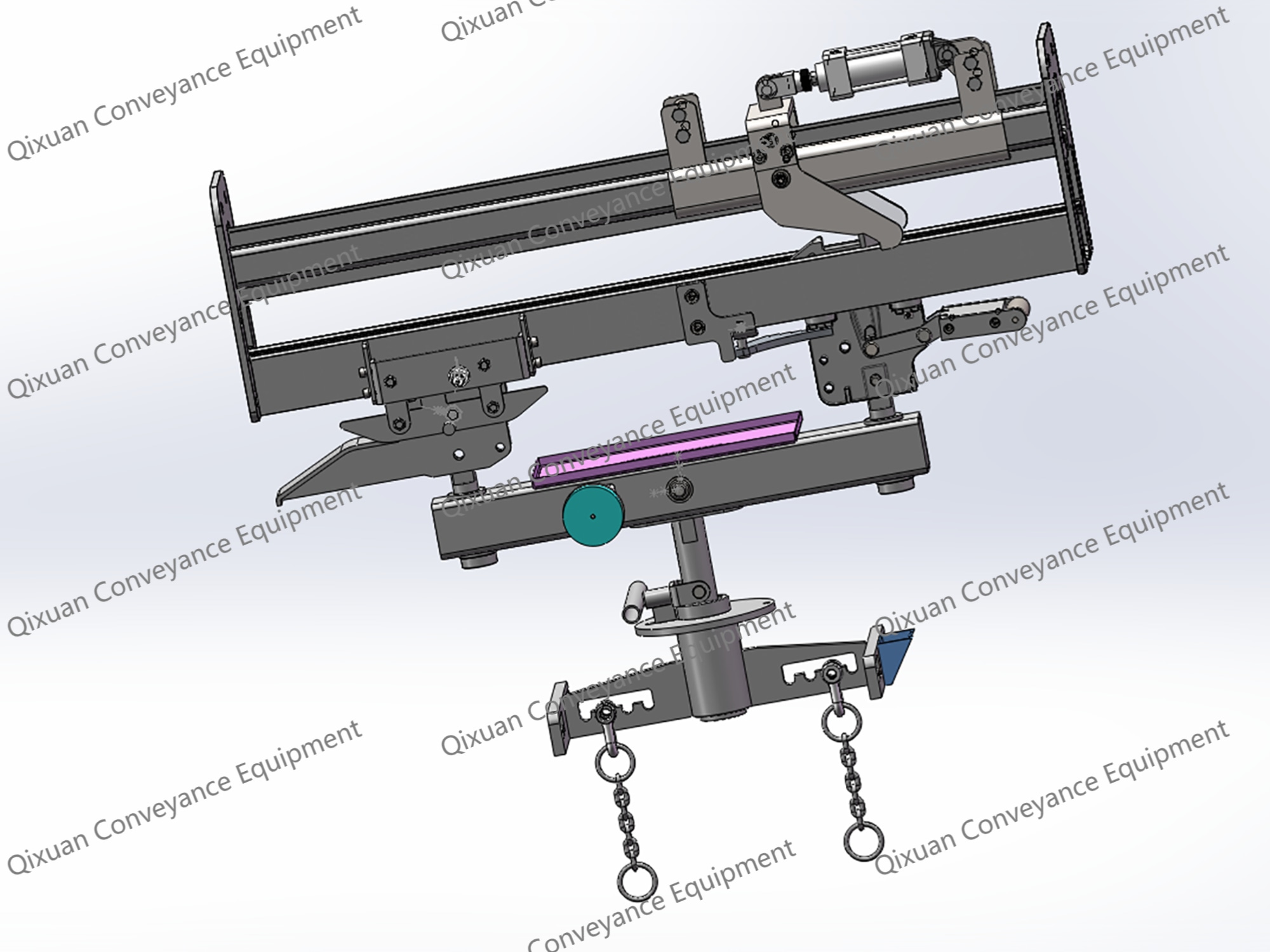
7. Stopper: Mounted on the”load track side”, controls trolley train movement at designated stops – ”core component for flow control”.
Key functions:
7.1”Safety interlock” (like traffic lights): Ensures safe trolley flow through switches.
7.2 ”Flow regulation”: Releases trolleys at controlled intervals on curves, slopes, and workstations to stabilize flow.
Operational principle:
– Extended stop arm depresses lifting dog → disengagement.
– Backstop dog rests on stop arm → trolley stops.
– Allows queuing of multiple trains behind stopped unit.
8. Stopper Types:
Stop arm actuation via ”pneumatic cylinder” mounted on stopper bracket. Two control modes:
– ”Automatic”(PLC/sensor-controlled)
– ”Manual”
9. Roller Turn Guide: Guides traction chain through horizontal curves with smooth transition. Structure:
-”Guide frame” parallel to traction track
– ”Roller battery” with precision bearings at equal intervals
– Roller quantity determined by ”curve radius”
Operation: Traction chain drives rollers via ”friction contact”along outer surfaces.
10. Sheave Turn Guide: A component guiding traction chains through horizontal curves with ”zero-interference transition”.
– ”Sheave”: Flanged flat disc with ”hub bearing” at center
– ”Traction chain” runs along sheave periphery via ”friction drive”
– ”Critical installation”: Must be leveled to prevent chain derailment
11. Switch (Track Switch): Controls trolley routing at ”track junctions” in P&F systems.

No comment